If, like me, you have started using Crowdsec on your linux servers and you also use Shorewall and Shorewall6 for managing your iptables rules, you will have no doubt found that there is no native bouncer available in the crowdsec repo. I found a blog post at http://www.sysadminguide.net/crowdsec-and-shorewall/ which contained a bash script to be used with the crowdsec-custom-bouncer, but as I use both IPv4 and IPv6 on my servers, this script did not work. So I have modified the script to the below and have been testing it successfully for a few days now. Feel free to use this if it is of use to you.
#!/bin/sh
#
# Script to add /remove IPs to shorewall blacklist

#determine action
if [ "$1" = "add" ]; then
if [[ "$2" =~ .*[.].* ]]; then
logger -t crsec-shorewall4 "add $2 for $3 with $4"
shorewall drop "$2"  > /dev/null 2>&1
elif [[ "$2" =~ .*[:].* ]]; then
logger -t crsec-shorewall6 "add $2 for $3 with $4"
shorewall6 drop "$2"  > /dev/null 2>&1
fi
elif [ "$1" = "del" ]; then
if [[ "$2" =~ .*[.].* ]]; then
logger -t crsec-shorewall4 "del $2 for $3 with $4"
shorewall allow "$2"  > /dev/null 2>&1
elif [[ "$2" =~ .*[:].* ]]; then
logger -t crsec-shorewall6 "del $2 for $3 with $4"
shorewall6 allow "$2"  > /dev/null 2>&1
fi
else
logger -t crsec-shorewall "unknon action"
fi
Save the above code into a file such as /etc/crowdsec/bouncers/crsec-shorewall.sh and make it exectuable. Next edit the /etc/crowdsec/bouncers/crowdsec-custom-bouncer.yaml file and edit the line bin_path: to read
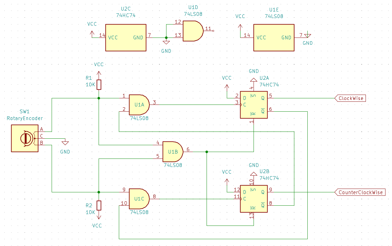
While trying to come up with a reliable solution for a project where I was using a Micro-controller and a Rotary Encoder and the signals from the Rotary Encoder where anything but reliable, I came up with the following hardware circuit. The circuit will send a pulse out the appropriate pin depending upon the direction that the encoder is turned.
The solution uses only two IC's, a 7474 flip flop and a 7408 AND gate.
Theory of Operation
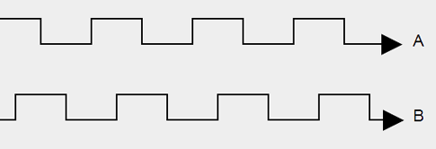
Simple Rotary Encoders are just two switches with a common ground that get switched on and off one at a time to create a basic binary operation. For example when turning the switch clockwise (figure 1), the sequence of operation is A goes Low, then B will go Low, then A will go High and finally B will go High completing the cycle.
Figure 1
When going counter clockwise, the process is reversed. First B goes Low, then A goes Low, then B goes High and finally A goes High completing the cycle.
The circuit operates in the following way when it receives the signals from the encoder.
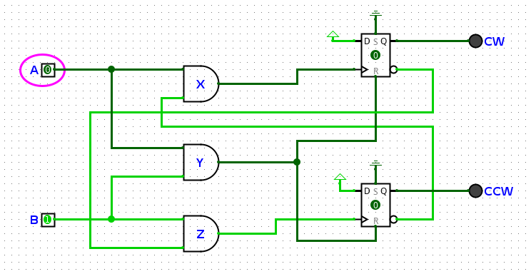
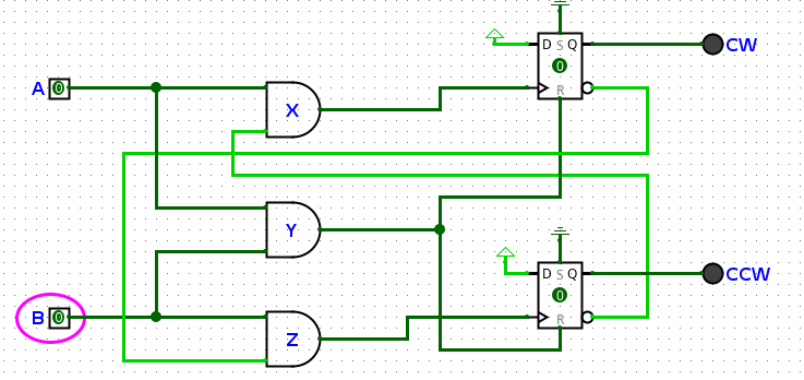
Figure 2
Figure 2 above shows the idle status where the encoder is not being turned either way.
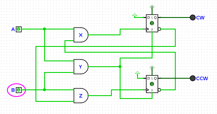
Figure 3.
Figure 3 shows the encoder being turned clockwise. The first state is that pin A has gone LOW. This causes the AND gates X and Y outputs to go LOW. With the AND gate Y going LOW, the R line to go LOW and activates the flip flops.
Figure 4.
Figure 4 shows the next stage of the encoder being turned clockwise. In the part of the operation, pin B goes LOW causing the AND gate Z to go LOW.
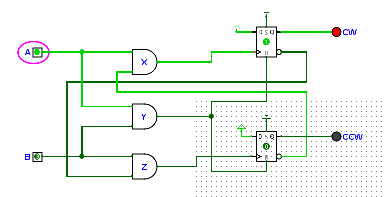
Figure 5.
Figure 5 shows the next step where pin A goes HIGH. This causes the output of AND gate X to go HIGH which clocks a HIGH into Q of the CW flip flop. The inverted output of the CW flip flop goes LOW which is connected to the AND gate Z. This will prevents the CCW flip flop from clocking anything onto its output when it comes back to HIGH to complete the cycle.
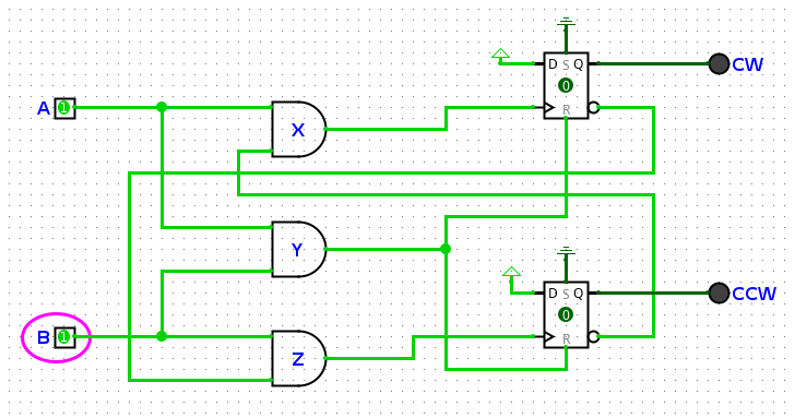
Figure 6.
The final step is pin B going HIGH again which cause the output of AND gate at Y to go HIGH which takes the R line of the flip flops to go HIGH. This resets the output of flip flop CW making Q go LOW and inverted Q to go HIGH. This places the circuit back into the original state ready for the next pulse.
We have designed a drop in replacement ic to replace the cxk5808. See our ebay listing here.
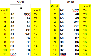
There is a Sony IC which is a 22pin 400mil package and is a 1k x 8bit SRAM that is not all that common, but is quite often faulty when found these days. It can be replaced with the more common 24pin 300mil 2k x 8bit SRAM such as the 6116, but requires that some of the pins are rewired due to the different packages.
The above image shows the pinouts of the 5808 along side the 6116.
You will notice that by moving the 5808 down 1 pin along side the 6116 that all the pins up to pin 16 match up. So the only pins that need to be changed are those below.
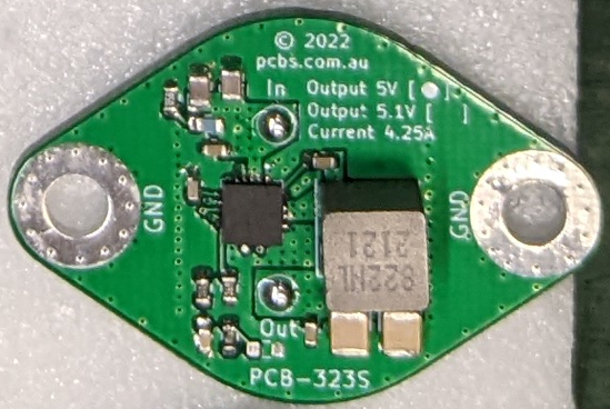
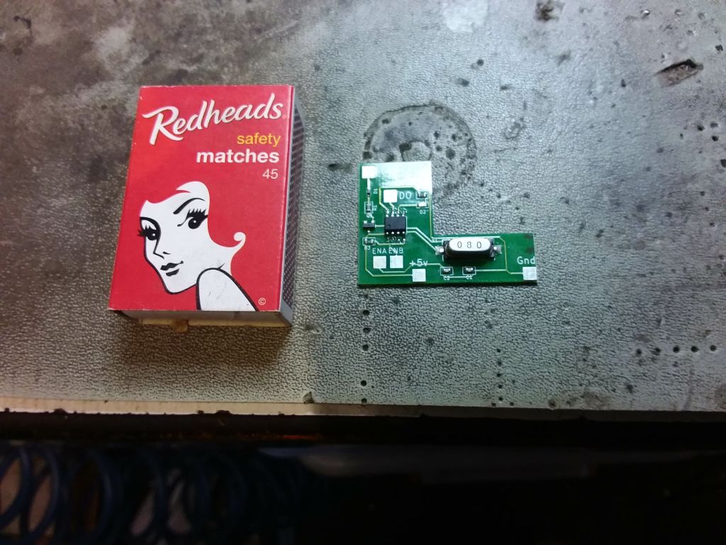
We have been working on a switch mode replacement for the now hard to get LM123, LM323 and other TO-3 5v regulators. Our replacement is capable of higher current and has much tighter tolerances than the original regulators and being switchmode runs a lot cooler.
Specifications.
Input Voltage: 7 – 34V
Output Voltage: 5v fixed (4.94 – 5.06)
Output Current: 4.25A continuous
Package Case: TO-3
Protection: Hiccup-Mode overload, Over Temperature, Short Circuit, Over Current, Under Voltage Lockout
Low Ripple: Measured at less than 40mV at full load
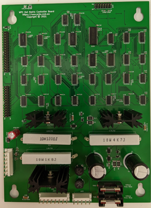
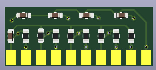
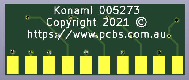
We have designed a replacement for those WPC DMD Controller Boards which are well known for burning PCB under the high voltage section. Our replacement board has a number of improvements to overcome these issues, including larger heatsinks which are spaced further apart, 10 Watt resistors instead of 5 Watt and they are spaced above the pcb with ceramic spacers to improve ventilation. All of the logic section has been remade using surface mount components.
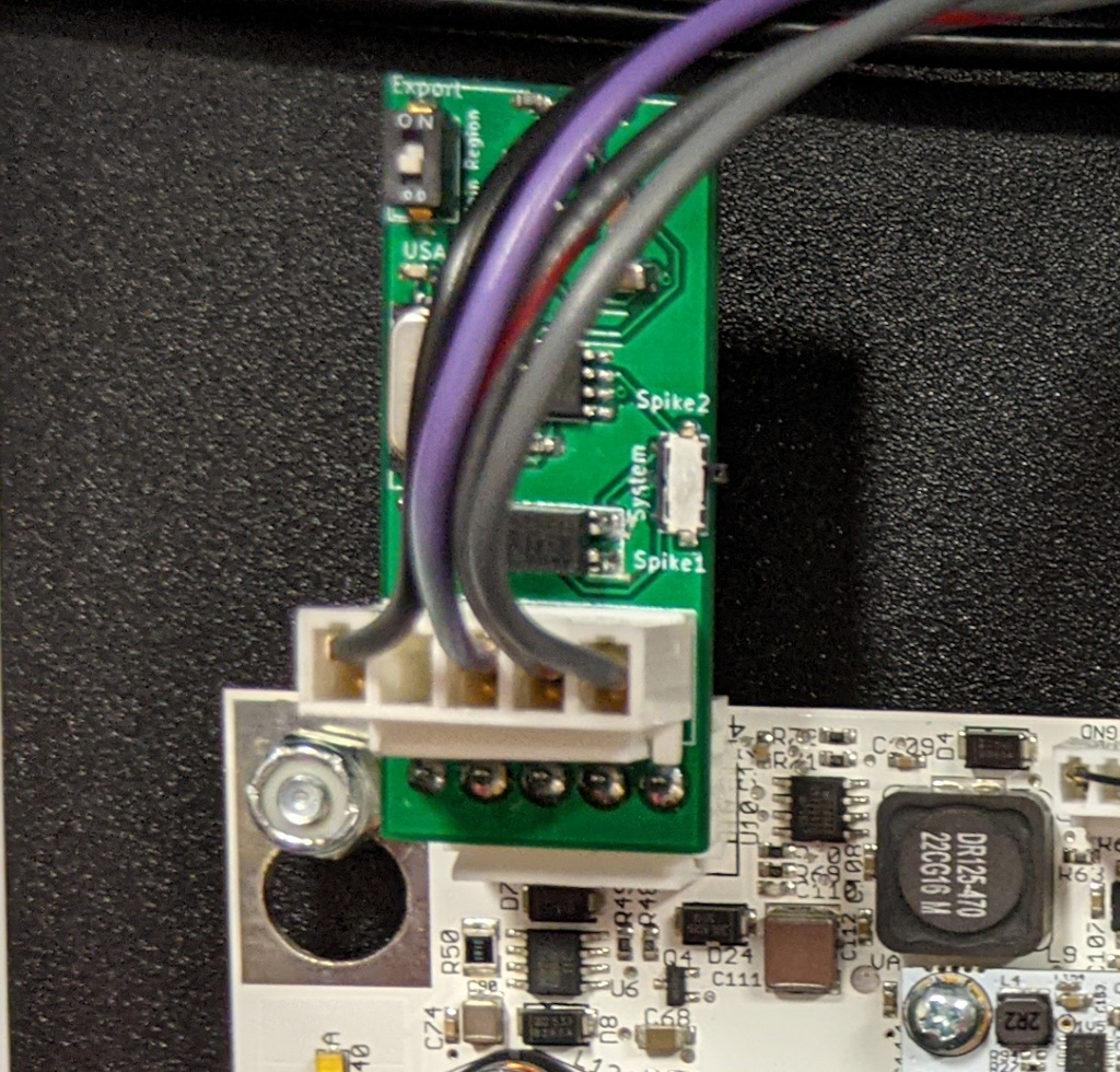
User GIBO over on the Aussie Arcade Pinball Forum has posted that he has a mod available for Stern Pinball machines purchased from the USA to be used in other countries and machines bought from other countries to be used within the USA.
The mod is made for the Spike2 system and from the looks of the image, there is no soldering required which is a real bonus for those who do not have the best soldering skills.
GIBO also has pictures of another mod in the same thread which he says will work with the Spike1 and SAM systems.
Fixes the error: This machine will not operate in this country Please contact your distributor.
The first time I put this board onto the workbench to have a look at it, there was a bit of corrosion on a few ICs. So before starting I gave the board a wash with SafeWash and then rinsed it off with Electronic Board Cleaner dried if off thoroughly. This removed the bulk of the corrosion and cleaned all the dirt and grime from the board.
Next I moved onto removing the ICs which had corrosion on them and replaced them. This included replacing G12, G13, G19 and F10.
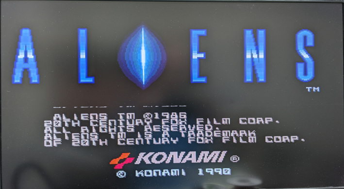
With the corrosion taken care of, I moved onto the eproms and checked them in the programmer. The IC at E24 tested fine, but the IC in C24 was not even from Aliens. So I pulled out a new 27C010 and programmed a new eprom and installed it.
Powering up the system resulted in a constant reset loop. I tested the voltage at some of the ICs and found that I was only getting about 4.7 volts. The Jamma connector on the board was very badly worn, so I increased the voltage on the bench power supply until I had close to 5v at the logic ICs.
Increasing the voltage stopped the board from resetting so rapidly, which was being caused by the power watchdog built into the 051550 module. However it was still rebooting. So it was time to start at the beginning and ensure that the system clock was running.
Firing up the CRO I was happy to see a steady 24MHz at pin 6 and 8 of IC G11. Next I checked around the 74245 at G19 to see if there was data between the CPU, SRAM and ROMs. Both sides of the 245 appeared to be quite active, so it was time to move onto the SRAM IC at locations G21 and G23 respectively.
The SRAM at G21 appeared to be working fine, but checking around G23 with the logic probe showed no activity at all on any of the data lines. I piggybacked G23 with a new SRAM and probed the data lines again, and this time there was plenty of activity. So I removed the faulty IC and installed the replacement.
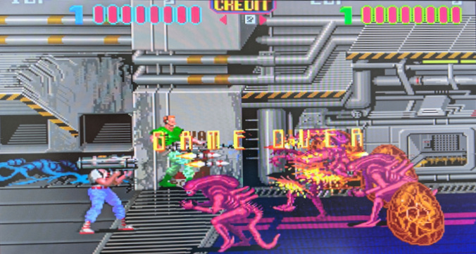
After powering up the board again I was greeted with the garbled screen with colour. It appeared as though the board was trying to run, but the video was bad. So I checked around the video SRAM at E14 and E15 and found the ram at E15 to have a number of dead data lines. I replaced the 16kb SRAM and fired up the board once again. This time the board came up with the test screen showing all the RAM and ROMs as being OK. I turned dip switch 3 on bank 3 to off and power cycled the board again and this time I was greeted with the game.
Letting the game run a bit and turning on sound in attract mode I noticed that there appeared to be some sounds missing. So I programmed a new IC for position D5 and replaced the original mask rom and the final issue was resolved.
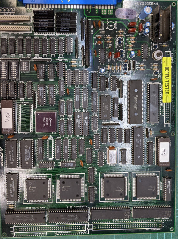
When I first got this board onto the bench and powered it up all I got was a chirp from the speakers every second or so as the board was stuck in a reset loop.
Starting at the beginning, I checked that I had a working clock and that I have 5v at the logic chips. They both checked out ok, so I started to probe around the buffers and rams and found a lot of floating pins on the video ram at locations F14 and F15. These chips were removed and tested and confirmed to be dead. So new rams were installed and the board was powered on again.
As expected this did not change the actual fault, but now I was getting a screen flash up each time the board reset. I checked the other rams and found that the one at position F3 was also showing a lot of floating pins.
I removed this ram and tested it in the programmer and it too was dead. So a new chip was installed and the board powered up again. This time the fault changed to a ROM check screen showing that chips K06 and K07 (locations K13 and K19 respectively) were bad. Great I was making progress.
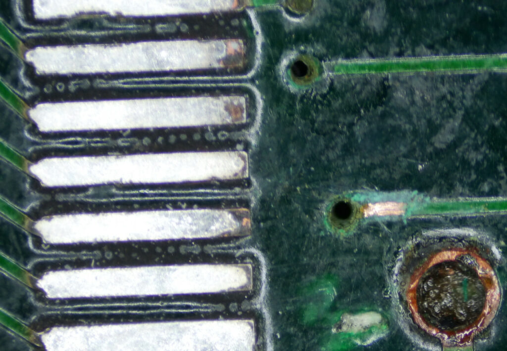
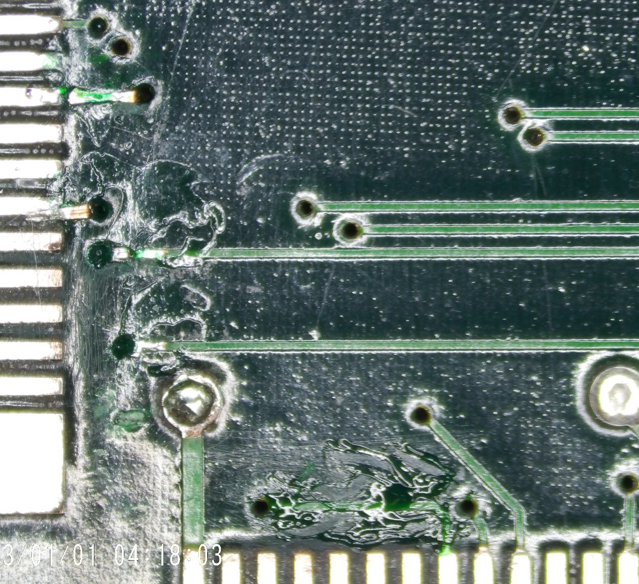
I started checking around those roms and noticed that they were addressed by the custom IC 052109. I also noted that there was two SRAMs which also went to the same custom IC. Checking around the rams showed that I had a number of inactive data lines on the rams. I traced the data lines between the ram and the custom IC and found there was 2 lines which were open circuit. Once again corrosion had eaten through some vias. Unfortunately they were both directly underneath this custom chip.
Although I do no like having to remove these custom chips, it was either remove it and repair the vias, or run fairly long wires to the custom chip which I do not think looks very good from a repair stand point.
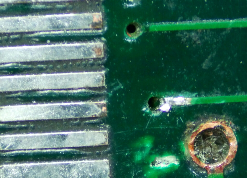
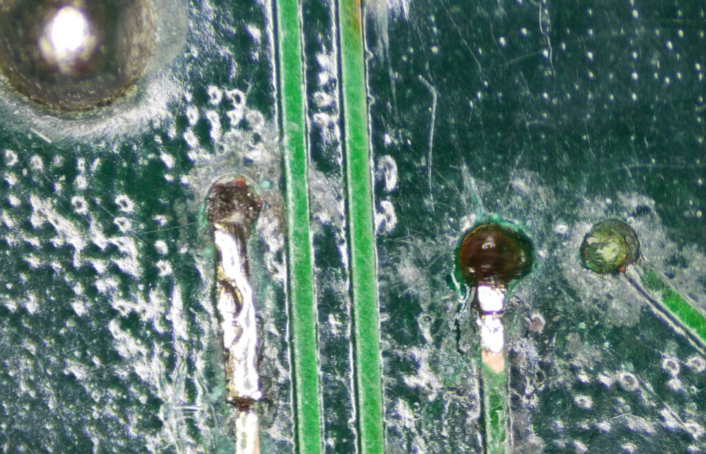
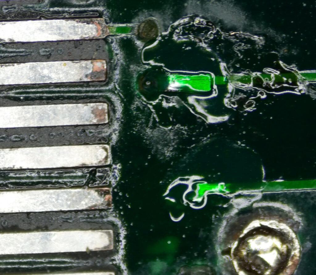
So off the chip came and now I was able to see just how bad these vias were. There was almost no copper left, even inside the hole itself. So I cleaned up the holes and removed the solder mask on the tracks on the top and bottom of the board and ran some new copper track through the holes and soldered them in place.
Finally putting some new solder mask over the repair to protect it from corroding again.
Before reinstalling the custom IC, I decided it prudent to check all the connections from the 120 pin custom IC to ensure there was no more broken vias. It took a couple of hours to go around all the pins and trace them out, but it was time well spent as I did find another couple of corroded vias which were no longer connected. Repairing these final couple of vias I was ready to reinstall the custom IC.
I reinstalled the custom IC and fitted sockets for the mask roms at K13 and K19 and prepared to power up the board again and see if my repairs had been successful. Powering it on again, I was greeted with a rom test screen showing me that the roms were ok.
Success! I turned off the test dip switch and power cycled the board expecting to be greeted with yet more faults, but low and behold, the game was working.
There was no sound, so turning on dip switch 8 on bank 2 and powering up the board again confirmed that the audio was also working. However there was quite a bit of hum in the audio. These old boards have a habit of having the 12v filter capacitors damaged during handling and storing. So I replaced the capacitor and fired it up again, and this time the hum was gone. Another successful repair and thanks to taking that extra bit of time and effort, the board still looks like its hardly been worked on.