While trying to come up with a reliable solution for a project where I was using a Micro-controller and a Rotary Encoder and the signals from the Rotary Encoder where anything but reliable, I came up with the following hardware circuit. The circuit will send a pulse out the appropriate pin depending upon the direction that the encoder is turned.
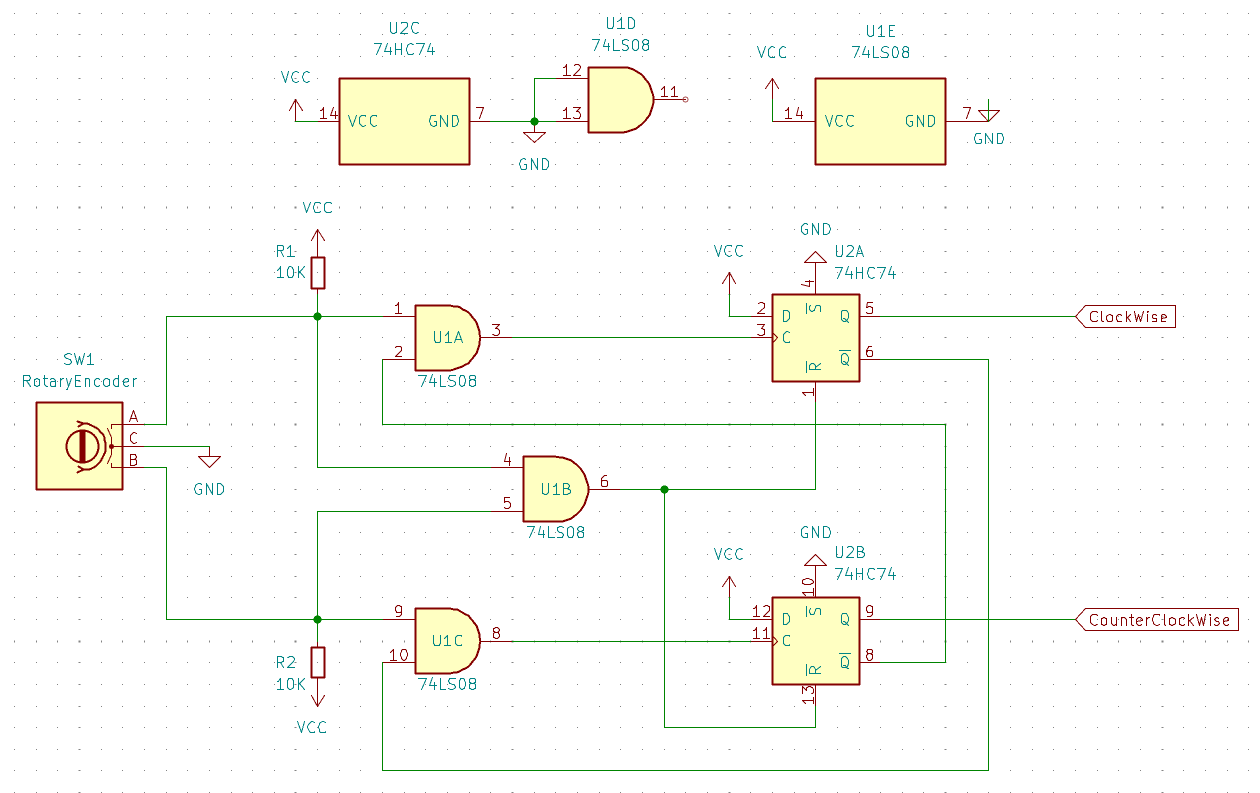
The solution uses only two IC's, a 7474 flip flop and a 7408 AND gate.
Theory of Operation
Simple Rotary Encoders are just two switches with a common ground that get switched on and off one at a time to create a basic binary operation. For example when turning the switch clockwise (figure 1), the sequence of operation is A goes Low, then B will go Low, then A will go High and finally B will go High completing the cycle.
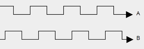
When going counter clockwise, the process is reversed. First B goes Low, then A goes Low, then B goes High and finally A goes High completing the cycle.
The circuit operates in the following way when it receives the signals from the encoder.
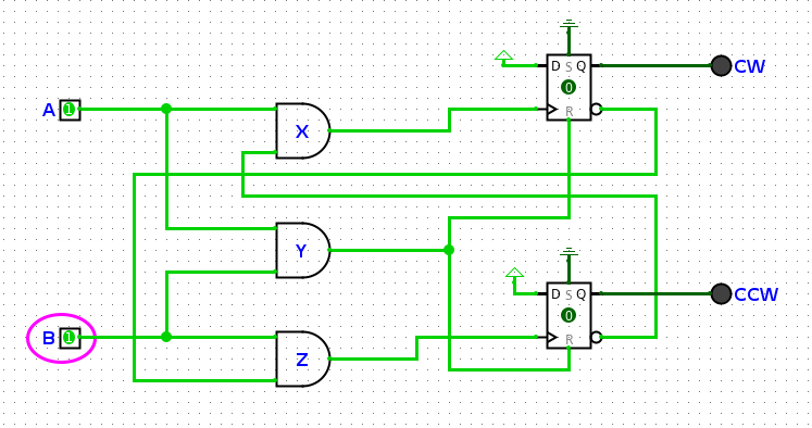
Figure 2 above shows the idle status where the encoder is not being turned either way.
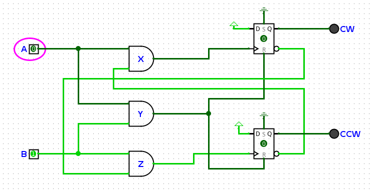
Figure 3 shows the encoder being turned clockwise. The first state is that pin A has gone LOW. This causes the AND gates X and Y outputs to go LOW. With the AND gate Y going LOW, the R line to go LOW and activates the flip flops.
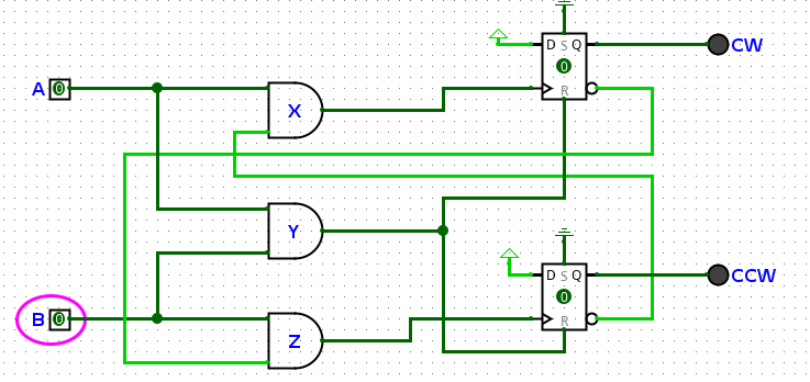
Figure 4 shows the next stage of the encoder being turned clockwise. In the part of the operation, pin B goes LOW causing the AND gate Z to go LOW.
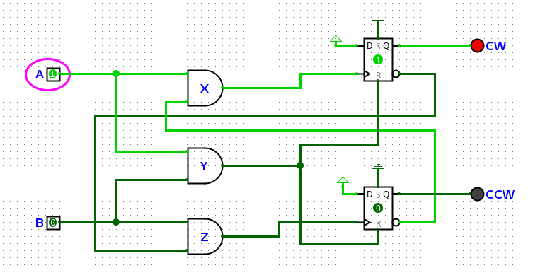
Figure 5 shows the next step where pin A goes HIGH. This causes the output of AND gate X to go HIGH which clocks a HIGH into Q of the CW flip flop. The inverted output of the CW flip flop goes LOW which is connected to the AND gate Z. This will prevents the CCW flip flop from clocking anything onto its output when it comes back to HIGH to complete the cycle.
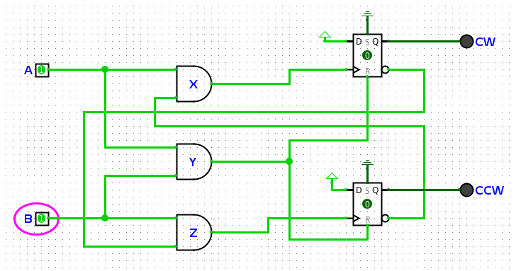
The final step is pin B going HIGH again which cause the output of AND gate at Y to go HIGH which takes the R line of the flip flops to go HIGH. This resets the output of flip flop CW making Q go LOW and inverted Q to go HIGH. This places the circuit back into the original state ready for the next pulse.