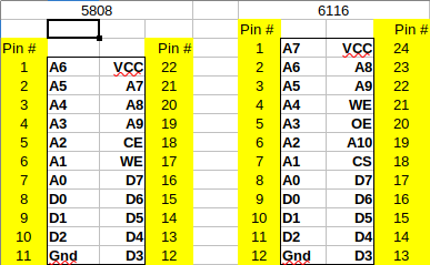
There is a Sony IC which is a 22pin 400mil package and is a 1k x 8bit SRAM that is not all that common, but is quite often faulty when found these days. It can be replaced with the more common 24pin 300mil 2k x 8bit SRAM such as the 6116, but requires that some of the pins are rewired due to the different packages.
The above image shows the pinouts of the 5808 along side the 6116.
You will notice that by moving the 5808 down 1 pin along side the 6116 that all the pins up to pin 16 match up. So the only pins that need to be changed are those below.
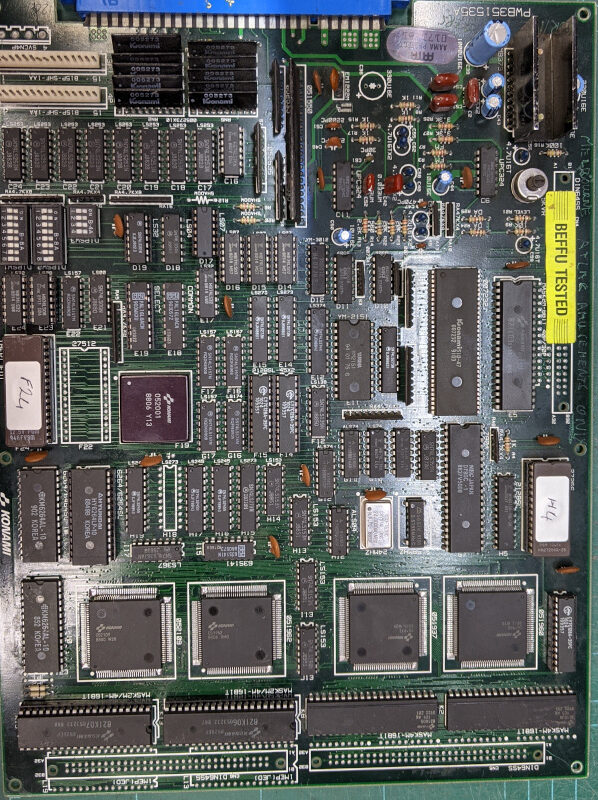
The first time I put this board onto the workbench to have a look at it, there was a bit of corrosion on a few ICs. So before starting I gave the board a wash with SafeWash and then rinsed it off with Electronic Board Cleaner dried if off thoroughly. This removed the bulk of the corrosion and cleaned all the dirt and grime from the board.
Next I moved onto removing the ICs which had corrosion on them and replaced them. This included replacing G12, G13, G19 and F10.
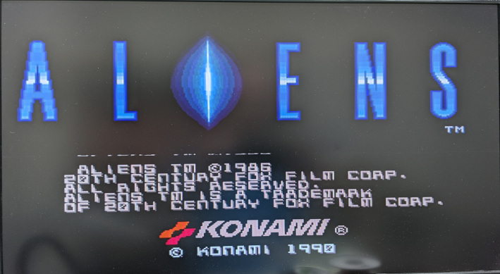
With the corrosion taken care of, I moved onto the eproms and checked them in the programmer. The IC at E24 tested fine, but the IC in C24 was not even from Aliens. So I pulled out a new 27C010 and programmed a new eprom and installed it.
Powering up the system resulted in a constant reset loop. I tested the voltage at some of the ICs and found that I was only getting about 4.7 volts. The Jamma connector on the board was very badly worn, so I increased the voltage on the bench power supply until I had close to 5v at the logic ICs.
Increasing the voltage stopped the board from resetting so rapidly, which was being caused by the power watchdog built into the 051550 module. However it was still rebooting. So it was time to start at the beginning and ensure that the system clock was running.
Firing up the CRO I was happy to see a steady 24MHz at pin 6 and 8 of IC G11. Next I checked around the 74245 at G19 to see if there was data between the CPU, SRAM and ROMs. Both sides of the 245 appeared to be quite active, so it was time to move onto the SRAM IC at locations G21 and G23 respectively.
The SRAM at G21 appeared to be working fine, but checking around G23 with the logic probe showed no activity at all on any of the data lines. I piggybacked G23 with a new SRAM and probed the data lines again, and this time there was plenty of activity. So I removed the faulty IC and installed the replacement.
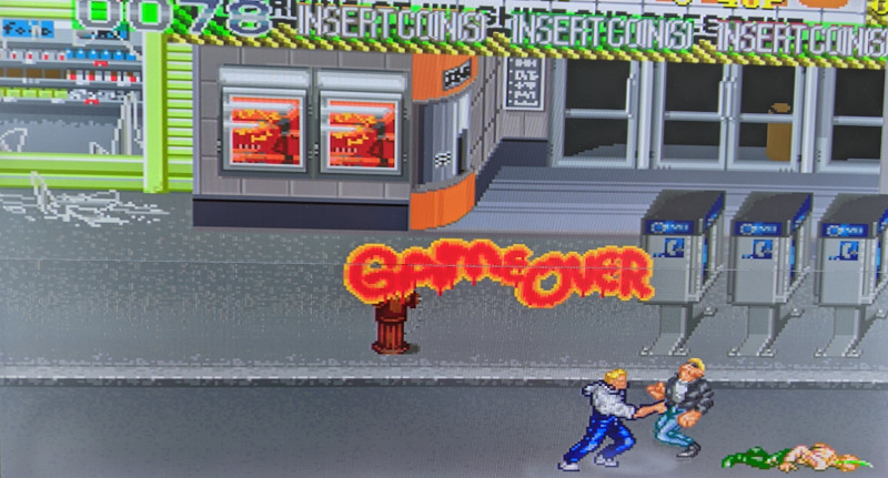
After powering up the board again I was greeted with the garbled screen with colour. It appeared as though the board was trying to run, but the video was bad. So I checked around the video SRAM at E14 and E15 and found the ram at E15 to have a number of dead data lines. I replaced the 16kb SRAM and fired up the board once again. This time the board came up with the test screen showing all the RAM and ROMs as being OK. I turned dip switch 3 on bank 3 to off and power cycled the board again and this time I was greeted with the game.
Letting the game run a bit and turning on sound in attract mode I noticed that there appeared to be some sounds missing. So I programmed a new IC for position D5 and replaced the original mask rom and the final issue was resolved.
When I first got this board onto the bench and powered it up all I got was a chirp from the speakers every second or so as the board was stuck in a reset loop.
Starting at the beginning, I checked that I had a working clock and that I have 5v at the logic chips. They both checked out ok, so I started to probe around the buffers and rams and found a lot of floating pins on the video ram at locations F14 and F15. These chips were removed and tested and confirmed to be dead. So new rams were installed and the board was powered on again.
As expected this did not change the actual fault, but now I was getting a screen flash up each time the board reset. I checked the other rams and found that the one at position F3 was also showing a lot of floating pins.
I removed this ram and tested it in the programmer and it too was dead. So a new chip was installed and the board powered up again. This time the fault changed to a ROM check screen showing that chips K06 and K07 (locations K13 and K19 respectively) were bad. Great I was making progress.
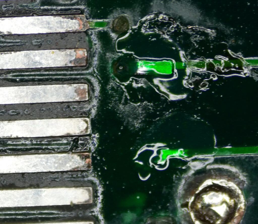
I started checking around those roms and noticed that they were addressed by the custom IC 052109. I also noted that there was two SRAMs which also went to the same custom IC. Checking around the rams showed that I had a number of inactive data lines on the rams. I traced the data lines between the ram and the custom IC and found there was 2 lines which were open circuit. Once again corrosion had eaten through some vias. Unfortunately they were both directly underneath this custom chip.
Although I do no like having to remove these custom chips, it was either remove it and repair the vias, or run fairly long wires to the custom chip which I do not think looks very good from a repair stand point.
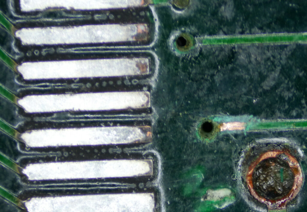
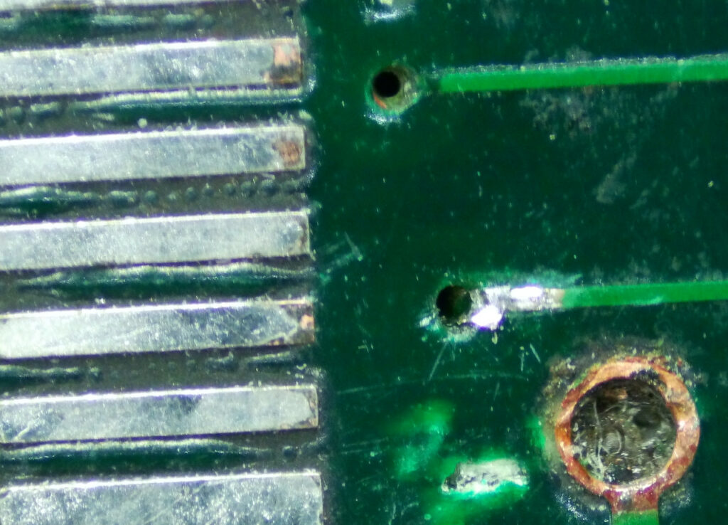
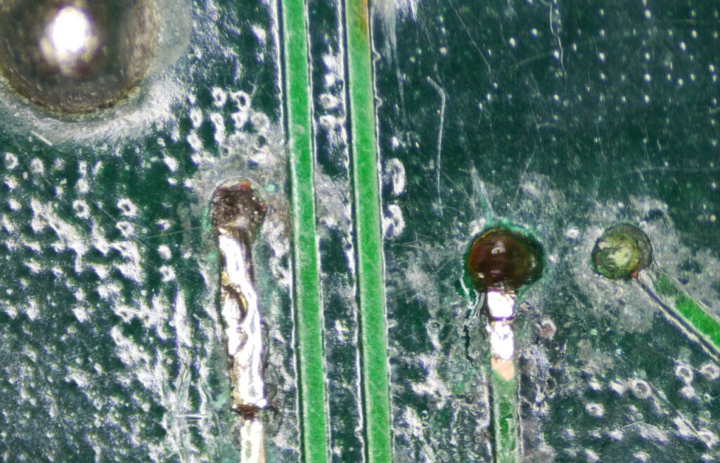
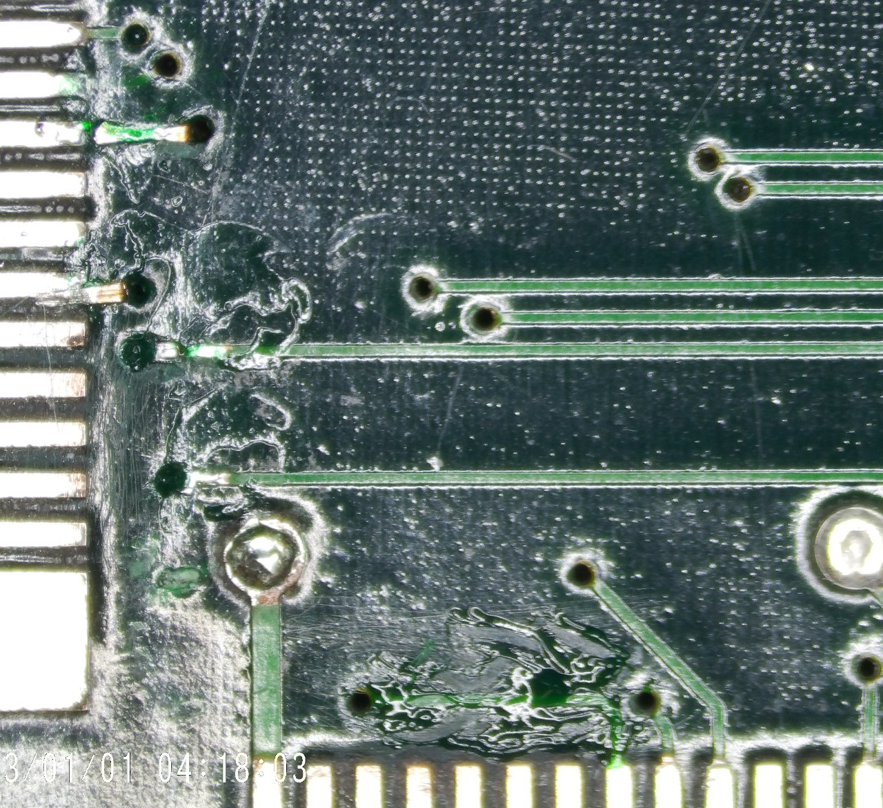
So off the chip came and now I was able to see just how bad these vias were. There was almost no copper left, even inside the hole itself. So I cleaned up the holes and removed the solder mask on the tracks on the top and bottom of the board and ran some new copper track through the holes and soldered them in place.
Finally putting some new solder mask over the repair to protect it from corroding again.
Before reinstalling the custom IC, I decided it prudent to check all the connections from the 120 pin custom IC to ensure there was no more broken vias. It took a couple of hours to go around all the pins and trace them out, but it was time well spent as I did find another couple of corroded vias which were no longer connected. Repairing these final couple of vias I was ready to reinstall the custom IC.
I reinstalled the custom IC and fitted sockets for the mask roms at K13 and K19 and prepared to power up the board again and see if my repairs had been successful. Powering it on again, I was greeted with a rom test screen showing me that the roms were ok.
Success! I turned off the test dip switch and power cycled the board expecting to be greeted with yet more faults, but low and behold, the game was working.
There was no sound, so turning on dip switch 8 on bank 2 and powering up the board again confirmed that the audio was also working. However there was quite a bit of hum in the audio. These old boards have a habit of having the 12v filter capacitors damaged during handling and storing. So I replaced the capacitor and fired it up again, and this time the hum was gone. Another successful repair and thanks to taking that extra bit of time and effort, the board still looks like its hardly been worked on.
The first time I powered up the system it was totally dead. No video and the CPU would try to start then halt.
I removed and checked the main EPROMs 18E, 18G, 8E and 8G and was happy to find that they all verified ok, but all of them had bent legs which had missed the socket and folded up underneath the IC. Luckily the legs did not break off when straightening them out and reinserting them into their respective sockets.
Unfortunately someone had attempted a repair in the video section and had removed the SRAM and buffers at 11D, 12D, 13D and 14D. When removing those ICs they had damaged a number of traces. They had attempted to repair the traces, however their repair was far from successful as they had connected traces to the wrong locations.
I removed all these ICs again and repaired all the traces and installed IC sockets. I also tested the SRAM and the buffers and found that one of each of was faulty, which was not at all surprising seeing as they were Fujitsu branded, so I replaced them with new ICs.
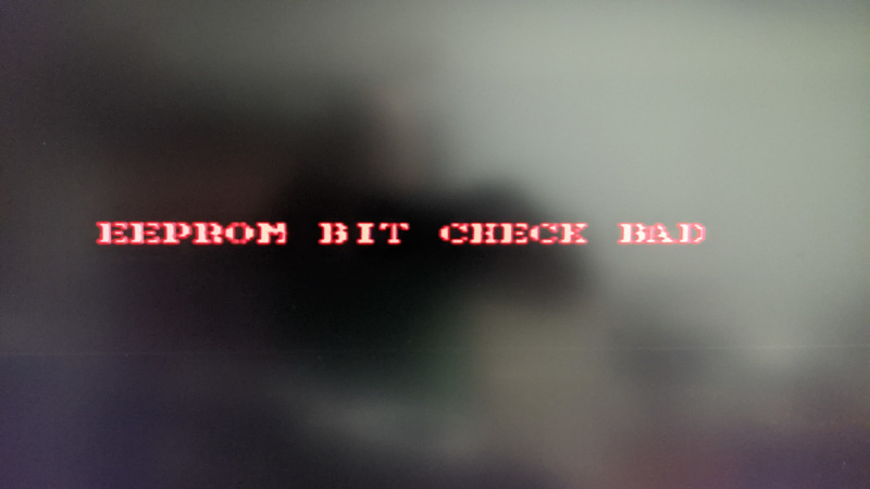
Happy that the previous repair attempt was now fixed, I moved to looking at the reason it was not booting. Checking the buffers at 13F and 14F showed data on the inputs but all the output lines were totally dead. Once again, they were Fujitsu, I removed and tested these buffers and they were both dead, so I replaced them and the system now booted, coming up with an error on the screen “EEPROM BIT CHECK BAD”.
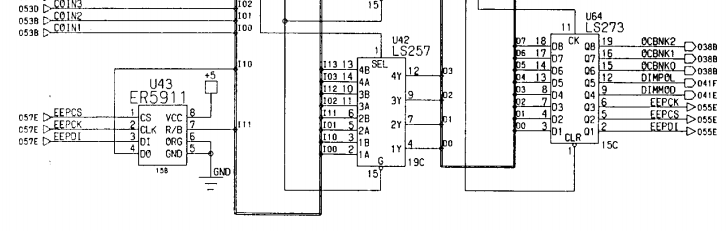
I checked the serial eeprom at 15B and found that there was no activity so whatever was meant to be reading it was not working. Referring to the schematic shows that the eeprom is addressed by the 74273 at location 15C.
I piggy backed the 273 and checked around the eeprom again with the logic probe and this time I had a clock on pin 6, but other lines were still inactive. Not really all that surprising, so I removed and replaced the Fujitsu 74273 and then system booted past the eeprom bit check bad error and gave me a new error to investigate.
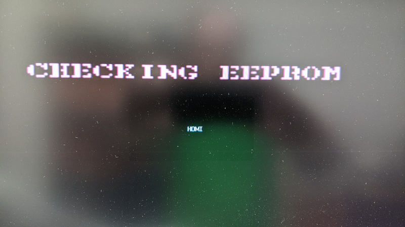
At first I was greeted with a checking eeprom screen. At this point I was thinking I had been lucky and the board was fixed, but that was not to be the case.
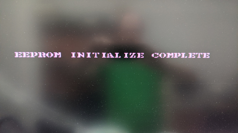
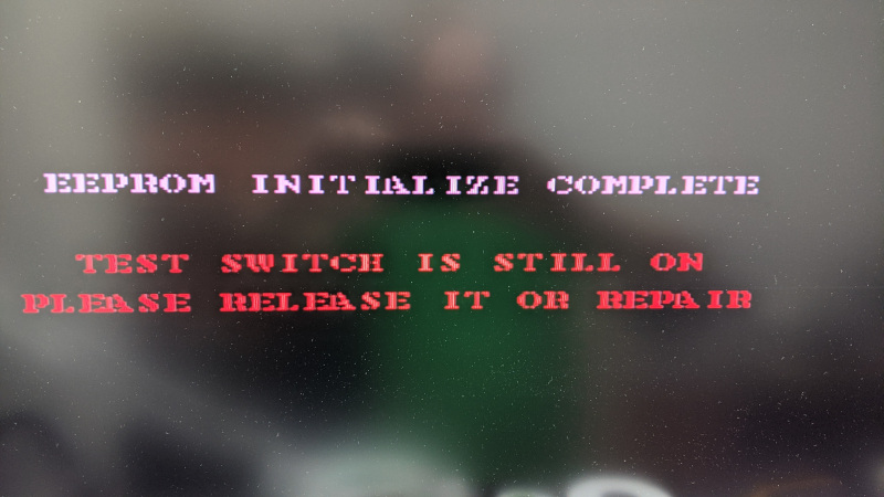
After about 10 seconds another screen saying eeprom initialize complete displayed.
Then finally I was greeted with an error message saying that the test switch was still on.
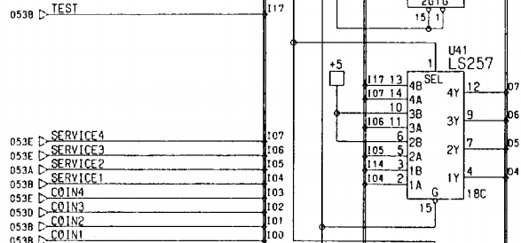
A quick check of the schematic shows that the test switch goes into pin 13 of IC 18C and the data line goes out on pin 12.
Probing those lines showed that the input was working fine, but the output had no activity. Time to replace another faulty Fujitsu IC.
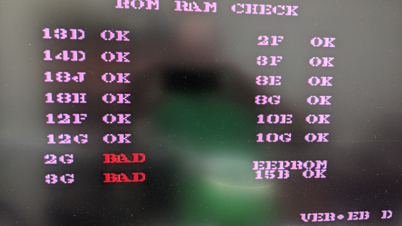
This time around the board booted to display the rom and ram check screen. Unfortunately it showed 2G and 3G were bad.
I began probing around those suspected bad SRAMs with the logic probe and found almost no activity whatsoever. Unfortunately the schematic I had did not show these SRAMs so I was unsure of where they went. However I had a hunch that two buffers at locations 8J and 8K probably had something to do with them and that they were likely to be faulty seeing as they were yet again, you guessed it, Fujitsu. So I piggy backed these two ICs, and this time I was greeted with a game screen. I replaced the buffers and turned the system back on and this time, I had no green or blue. It turned out that a number of 7407s at locations 8C, 9C, 10C, 11C and 12C had failed while I had been performing the repair. Not all that surprising given that they are all also Fujitsu. Rather than replacing just the faulty ones, I just replaced all of them which gave me back all the colours.
Now the game was running, but I could see there was still another fault. On certain screens there was a black bar.
Now the game was working I could go into the menu and test the mask roms to see if that was the problem. Unfortunately that was not to be. When pressing the test button, I could get into test, but the start button would not work. You guessed it, time to replace more Fujitsu ICs. After replacing most of the 74253 and 74257 ICs at locations 13B, 14B, 16C, 17C and 19C I was finally able to run the mask rom test and was surprised when it returned ok for all the roms.
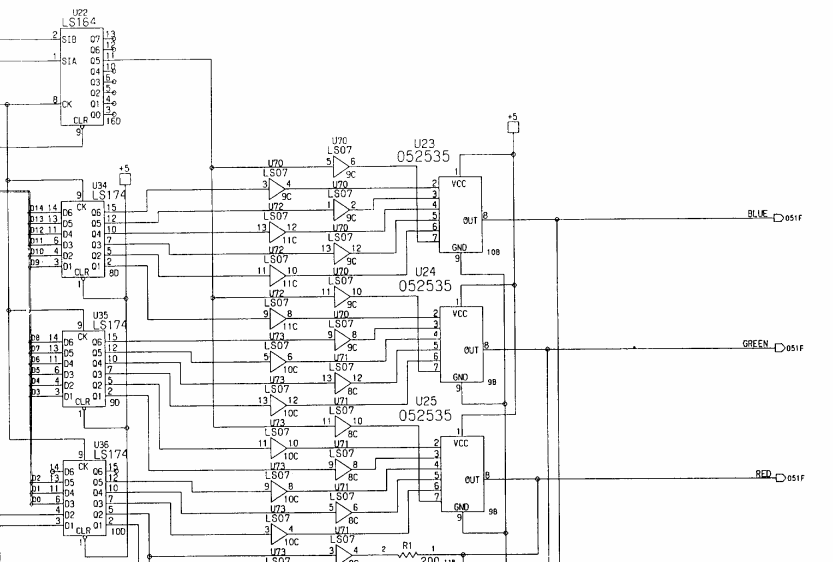
Given the roms were all testing ok, I decided to review the schematic again and this time I notice the 74164 at location 16D, a serial in, parallel out shift register, of which output pin 11 goes to pin 7 on all three colour modules through a 7407.
I put the logic probe onto pin 11 of IC 16D and found it to be totally dead. Checking the inputs on pin 1 and 2 showed plenty of activity. So I removed the ic and tested it in the programmer and sure enough it was completely dead. Replacing the 74164 with a new one, I powered up the system once again and this time it was working properly.
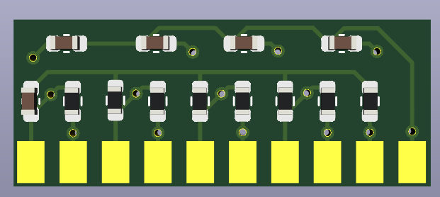
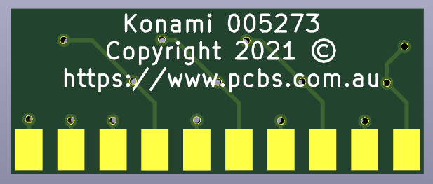
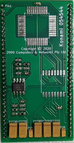
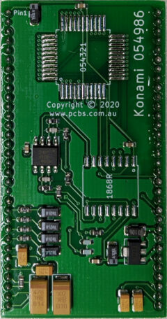
I have reproduced the Konami modules for the below games. Replacing these modules has become a must as the original modules are covered in a conformal coating and the surface mount electrolytic capacitors are failing and corroding the very thin tracks away. Left for long enough they will even damage the game board that they are installed in.
The modules do not come with the DAC or the ASIC chips, they need to be taken off the old module and installed onto the new one, so being comfortable with surface mount rework is a must to successfully change this module.
These reproduction boards have been designed so that all components are located on the top side of the board, unlike the original board and some of the other reproductions out there which has components on both the top and bottom of the board. Our modules use only Tantalum capacitors which eliminates the possibility of capacitors leaking corrosive materials in the event of failure.